
Mounting type is the most consequential decision in a cylinder specification and the one most often copied from the previous machine. It decides whether the cylinder survives misalignment, whether the rod buckles at full extension, and how long a mechanic spends changing it.
There are six common mounting families and three questions that choose between them.
Three questions, in order
Where does the reaction force go? A mount transmits the cylinder force into the machine structure. Flange and foot mounts put it into a face or a base; clevis and trunnion put it into a pin. The machine structure has to be able to take it, and that is usually the constraint nobody checks.
Is there any misalignment? Real frames flex and real brackets are welded in the field. A mount that cannot rotate transmits that misalignment into the rod as a bending moment. A mount that can rotate absorbs it.
How will it be removed? A clevis pin comes out with a hammer. A flange comes out after the surrounding structure comes out. On equipment where the cylinder is a wear part, service access should decide the mount as much as the load does.
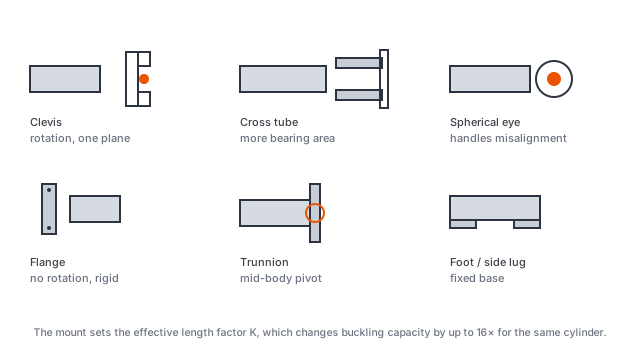
The six families
| Mount | Rotation | Typical use | Weakness |
|---|---|---|---|
| Clevis (fork) | Yes, one axis | tail lift, linkage, steering | pin bore wears; needs lubrication |
| Trunnion | Yes, one axis, mid-body | long-stroke luffing, crane boom | needs clearance at the pivot |
| Rectangular / square flange | No | fixed machinery, presses | no tolerance for misalignment |
| Side lugs | No | short stroke, low side load | shear in the mounting bolts |
| Foot mounting | No | stationary plant | bolted joint works loose under shock |
| Extended tie rods | No | compact industrial cylinders | tie rods take the load, not the barrel |
ISO 6020/2 assigns codes to these geometries — MF1 and MF2 for rectangular flange, MF3 and MF4 for square, MS2 for side lugs, MP1 for foot, MP3 and MP5 for trunnion, ME5 and ME6 for extended tie rods, MT4 for clevis. The code letters matter for interchangeability: two cylinders with the same code, the same bore and the same stroke should be mechanically interchangeable. That is the reason to specify by code rather than by picture.
Rotation is the property that matters. Clevis and trunnion mounts allow the cylinder to swing as the load line moves, which is why they appear on almost every application with a linkage or a boom. Flange, foot and lug mounts do not. If a fixed mount is used where the geometry moves, the rod takes a bending moment on every stroke and the gland wears oval — a failure that looks like a seal problem and is actually a mounting problem.
Rod end types
The rod end has the same choice. A plain eye takes a pin and allows rotation in one plane only. A spherical bearing — a rod eye with an internal spherical plain bearing — allows a few degrees of angular error in any direction, and is the standard fix for field-welded brackets.
The trade is load capacity: a spherical bearing has a lower static load rating than a plain eye of the same size. On a cylinder that already has margin, spend it on the spherical bearing. On a cylinder sized to the limit, keep the plain eye and fix the alignment.
Side load and the rod
No cylinder is designed to take continuous side load. Where the geometry produces it — a boom, a conveyor plough, a refuse packer — three things absorb it:
- A larger rod. Rod diameter governs bending stiffness, and stiffness goes with the fourth power of diameter. Going from a 50 mm rod to a 63 mm rod increases bending stiffness by a factor of about 2.5.
- A wear ring in the gland. The stop-tube wear ring keeps the rod from metal-to-metal contact and gives the side load somewhere to go that is not the seal.
- A stop tube. A spacer between the piston and the gland increases the distance between supports at full extension, which increases the unsupported length and therefore reduces buckling capacity. This is the tension in the design: a stop tube helps wear and hurts buckling. Use it only where side load, not column stability, is the risk.
Worked buckling check
Take a cylinder with a 1,307 mm power stroke and a 543 mm closed dimension, which is the 4TG-E130×1307 in the underbody range. Extended length is about 1,850 mm. Assume a 70 mm rod.
Rod cross-section properties: the second moment of area is I = πd⁴/64 = π × 0.070⁴ / 64 = 1.179 × 10⁻⁶ m⁴.
With clevis mounts at both ends, the column is pinned-pinned and the effective length factor is K = 1. Euler load:
Pcr = π²EI / (KL)² = π² × 206 × 10⁹ × 1.179 × 10⁻⁶ / 1.85² ≈ 700 kN
The radius of gyration of a solid rod is r = d/4 = 17.5 mm, so the slenderness ratio is KL/r = 1,850 / 17.5 ≈ 106. That is above the transition slenderness for steel (roughly 80 to 100 depending on yield strength), so Euler applies and the result is trustworthy rather than optimistic.
Now compare to the working load. At 180 bar on a 130 mm effective diameter, force is about 239 kN. The buckling safety factor is 700 / 239 ≈ 2.9.
Two things follow. First, at these proportions buckling is not the constraint — a factor of 2.9 on a pinned column is comfortable. Second, if the same cylinder were mounted with fixed supports at both ends, K = 0.5 and the buckling load would be four times higher. But if it were mounted with one end fixed and the rod end free to move laterally, K = 2 and capacity drops by a factor of four.
The mount changes buckling capacity by a factor of sixteen between K = 0.5 and K = 2. That is a larger effect than almost anything else in the cylinder design, and it is decided entirely by how the cylinder is attached.
Choosing for the machine, not for the catalogue
A few practical rules cover most cases:
- Rotating mount wherever the geometry moves. Clevis or trunnion on anything with a boom, a linkage or a body that hinges.
- Fixed mount where alignment is guaranteed. Flange on machine tools, presses and any installation machined in one set-up.
- Spherical bearing at the rod end on field-welded installations. It absorbs the one or two degrees of error that no one can weld away.
- Never use the cylinder as a structural member. A cylinder holding a linkage in place under no pressure is carrying load it was not designed for; add a stop instead.
- Check the pin, not just the cylinder. Most cylinder “failures” on linkage equipment are worn pins and elongated bores, and a new cylinder in worn pins fails the same way.
Pin and boss dimensions are part of the mount
A mount is only as strong as its pin. Clevis pins fail in shear and in bending, and pin bores elongate from fretting long before either becomes visible. Specify pin diameter, pin material and whether the pin is hardened, and check the boss width on the mating part — a pin sized correctly but bearing on a narrow boss will wear the boss rather than the pin.
On refurbishment work, measure the existing pin bore before ordering a replacement cylinder. A cylinder built to nominal dimensions drops into an elongated bore with visible slop, and the new cylinder gets blamed for a machine problem.
What to specify
Mounting code per ISO 6020/2, rod end type, pin diameter, and whether the installation can guarantee alignment within about half a degree. Those four answers decide the mount, the rod diameter and whether a spherical bearing is needed — and they are the difference between a cylinder that lasts and one that is blamed.