
A truck-mounted crane is a holding machine that occasionally lifts. That single sentence explains most of the specification differences between crane cylinders and tipping cylinders, and it explains why crane hydraulics fail differently.
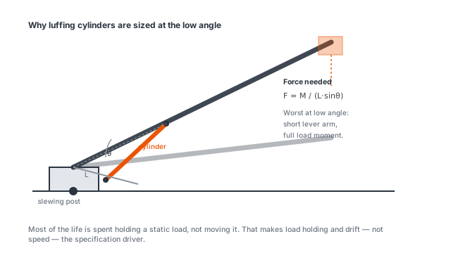
The load case is static, not dynamic
A tipper cylinder works for 30 seconds and rests for an hour. A crane cylinder holds a load at radius for minutes at a time, and holds it while the operator moves another function. The cylinder is pressurised continuously, which means the seals are under load continuously and the oil is being squeezed through the counterbalance valve the whole time.
Two consequences follow. First, internal leakage becomes a positioning problem rather than an efficiency one: a cylinder that bypasses 0.5 L/min will let a loaded boom creep down visibly over ten minutes. Second, the oil heats up from the throttling at the counterbalance, not from the pump doing work. Crane circuits routinely run 20 to 30 °C above ambient and that is normal; running 50 °C above ambient means the counterbalance is set too high or the reservoir is too small.
Bore, rod and what each one decides
The HSG series covers bore and rod combinations from 50/28 to 200/140 mm at 20 MPa, with stroke from 430 to 3,500 mm across 7 models. The bore sets force; the rod sets resistance to bending and the retract speed.
| Function | Typical bore/rod | Why |
|---|---|---|
| Outrigger / stabiliser | 50/28 to 80/45 mm | short stroke, force not the issue |
| Boom luffing | 100/70 to 160/110 mm | long stroke, bending governs |
| Main lift on heavy boom | 180/125 to 200/140 mm | force and rod stiffness together |
| Extension / jib | 63/36 to 90/50 mm | speed over force |
The rod ratio matters more on cranes than on most equipment because the extended rod is a cantilever. At 3,500 mm of stroke the rod is exposed to any side load the swinging load generates, and a rod that is merely strong enough in compression will still deflect enough to score the gland. A rod diameter of at least 0.7 times the bore on long-stroke crane cylinders is a reasonable starting point.
Counterbalance and hose burst protection
Every crane cylinder that carries a load needs a counterbalance valve mounted directly on the port, not in the valve block 3 metres away. Mounted on the cylinder, it protects the volume between the valve and the cylinder as well as the cylinder itself.
Setting matters as much as fitting. A counterbalance set too low lets the load run away when the control valve is feathered; set too high and it adds pressure on the rod side during retraction, which is a common cause of gland seal failure on cranes that seem to be “always leaking”. Start at 1.3 times the load-induced pressure at the worst radius and adjust from there.
An overcentre valve with a pilot ratio around 3:1 is the usual choice for boom luffing. It opens progressively and does not chatter at low flow, which a plain counterbalance does.
Power source: PTO or standalone
Most truck cranes run from a PTO-driven pump on the truck gearbox, and in that case the DC power unit has no role. Where the crane is fitted to a trailer, a hooklift chassis or a static base without an engine, the DC hydraulic power unit covers 12 V or 24 V supply, 0.75 to 8 cc/rev pump displacement, 3 to 25 L/min flow and 3 to 16 L reservoirs at 50 to 250 bar.
A 16 L reservoir with 25 L/min of flow is about 1.6 minutes of retention, which is thin for a crane running continuously. If a DC unit is driving a crane rather than a single-function tail lift, size the reservoir at three times the pump flow per minute, or accept an oil cooler.
Specification checklist
For a crane cylinder quote, send the boom drawing with the cylinder anchor points, the maximum load at maximum radius, the pump pressure available, and the number of functions that must move at once. Where two functions share a pump, the cylinder must be sized against the pressure that remains when both are moving, not the relief setting.
The model table on the HSG product page gives force and dimension data across the full bore range.