
A tail lift is the most cost-sensitive hydraulic application on a truck, and that constraint shapes every part of the design. The pump is small, the reservoir is small, and the whole system runs off a battery that also has to start the engine in the morning.
The circuit is deliberately simple
A liftgate circuit has a single-acting cylinder, a pump, a check valve, a lowering valve and a reservoir. Lifting is pump-driven; lowering is a controlled leak back to tank. There is no return line from the rod side because there is no rod-side oil to return.
That simplicity is why liftgate failures are so easy to diagnose and so often misdiagnosed. There are only four components that can cause a slow lift: a worn pump, a leaking check valve, a bypassing cylinder seal or a restricted suction line. A pressure gauge on the pressure port distinguishes them in about two minutes, and yet most slow lifts are reported as “the motor is weak” when the motor is the one part that rarely fails.
Battery current sets the specification
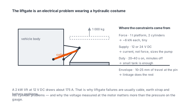
The number that decides whether a liftgate works reliably is current draw, not lifting force. A 12 V system lifting 750 kg needs roughly 1.5 kW at the motor, which at 12 V is about 125 A before efficiency losses and closer to 150 A at the terminals.
Three things follow. Cable size has to be calculated for 150 A over the run from battery to pump, not chosen by eye. The alternator has to carry the lift load in addition to the vehicle’s own demand, or the battery is discharging every time the gate moves. And the duty cycle has to be honest: a 12 V unit doing 30 lifts an hour on a multi-drop route will overheat, because the motor is rated for minutes of operation, not hours.
The 24 V version solves all three by halving the current for the same power. Above about 750 kg platform capacity, 24 V is the cheaper system once cable and alternator are counted.
Power unit specification
The DC hydraulic power unit covers 12 V or 24 V supply, pump displacements from 0.75 to 8 cc/rev, flow from 3 to 25 L/min, reservoirs from 3 to 16 L and working pressures from 50 to 250 bar with 180 bar as the standard setting. Ports are BSPP 1/4” or BSPP 3/8”, control is by cable or wireless remote, and the unit mounts horizontally or vertically.
For a tail lift, the pump displacement is chosen backwards from the required lift time. A 500 kg platform needing to rise 1,000 mm in 8 seconds at 12 V typically lands on a 1.5 to 2 cc/rev pump with a 4 to 6 L reservoir. Reservoir size is set by heat, not by volume: a liftgate that runs 20 cycles an hour needs at least 4 litres of oil to shed the heat from the throttling at the lowering valve.
Wireless remote control is worth specifying where the operator works alone. It removes the cable that is the single most common mechanical failure on tail lifts, and it costs less than the labour of replacing one cable a year.
Corrosion and the rod
A tail lift lives at the back of a truck, which means road spray, salt and grit are directed at the rod every time the vehicle moves. The rod seal and wiper are the wear parts, and a boot over the exposed rod is the cheapest life extension available.
Cylinder bodies are usually painted steel on this application, not stainless, because the cost matters more than the corrosion margin. That makes the paint specification part of the hydraulic specification: a two-coat system on a shot-blasted surface lasts several winters, a single coat over mill scale does not.
What to send for a quote
Platform capacity, lift height, required lift time, supply voltage and the number of cylinders. Those five answers determine the pump displacement, the reservoir, the cylinder bore and the current draw, and they can be checked against the model data on the power unit page in a few minutes.