
The force number on a datasheet is the force at the piston, at rated pressure, with no friction and no back pressure. Delivered force at the load is always lower, and on a telescopic cylinder it changes continuously through the stroke.
Both effects are easy to calculate and both are frequently ignored.
Push force
F = p × A
For a 130 mm effective diameter at 180 bar, the area is π/4 × 0.130² = 0.01327 m², and:
F = 18,000,000 × 0.01327 = 238,900 N ≈ 239 kN ≈ 24.4 t
That is the number to design against, and it is the number that should be checked against the tipping capacity shown in the model tables. The E130 underbody series lists 15 to 25 t of tipping capacity across its models, and the upper end of that band is what a 130 mm stage produces at 180 bar. The tables and the formula agree, which is how you know both are right.
Pull force is smaller
On the rod side, the pressure acts on the annulus — the bore area minus the rod area:
F = p × (A_bore − A_rod)
With a 70 mm rod in the same 130 mm bore, rod area is π/4 × 0.070² = 0.00385 m², so the annulus is 0.01327 − 0.00385 = 0.00942 m²:
F = 18,000,000 × 0.00942 = 169,600 N ≈ 170 kN ≈ 17.3 t
The pull-to-push ratio is 0.71. That ratio is set entirely by the rod-to-bore ratio, and it matters on any double-acting application where the retract stroke does work — a packer ram pulling back, a crane boom pulling down, a press opening.
A rod that is 0.7 of the bore gives a pull ratio of 0.51. A rod at 0.5 of the bore gives 0.75. Larger rods are better in buckling and bending and worse in pull force, and that tension is resolved by which stroke does the work.
If you want the numbers rather than the method, the cylinder force calculator takes bore, rod and pressure and returns push force, pull force and the area ratio.
What the load never sees
Three deductions sit between the theoretical force and the force at the pin.
Seal friction. Typically 3 to 7 percent of theoretical force on a well-built cylinder with a compact seal package, more on a cold start with cold oil. It is a real deduction and it is why a cylinder sized exactly to the load will sometimes stall on the first stroke of a winter morning.
Back pressure. The oil leaving the rod side has to get back to tank through a valve, a hose and possibly a counterbalance. That resistance is a pressure acting against the piston. On a circuit with a counterbalance set at 1.3 × load pressure, the back pressure term can be tens of bar, and every bar of back pressure costs the same force as a bar of supply pressure.
Line loss and elevation. Pressure at the cylinder is not pressure at the pump. A long hose run, a restrictive coupling or a cylinder mounted above the reservoir all reduce it. The loss scales with flow squared, so it bites hardest at high speed.
Add those and a cylinder that looks sized to the load on paper can be 15 to 20 percent short in practice. The usual approach is to size against 85 to 90 percent of the theoretical force, not 100 percent.
Telescopic cylinders do not deliver constant force
This is the part that catches people out. In a multi-stage cylinder, only the largest stage is pressurised at the start. When it bottoms out, the next smaller stage takes over. Since force is pressure times area, and each stage has a smaller area, the force falls in steps as the cylinder extends.
Take the three-stage FE series, which runs 158 / 136 / 115 mm bores at 16 MPa:
| Stage | Bore | Area | Force at 16 MPa |
|---|---|---|---|
| 1st | 158 mm | 0.01961 m² | 314 kN ≈ 32.0 t |
| 2nd | 136 mm | 0.01453 m² | 232 kN ≈ 23.7 t |
| 3rd | 115 mm | 0.01039 m² | 166 kN ≈ 16.9 t |
The cylinder delivers 32 t at the start of the stroke and 17 t at the end — the force halves from first stage to last. Meanwhile the speed goes the other way: velocity is flow divided by area, so as the area shrinks the cylinder extends faster.
That behaviour is not a defect, it is the mechanism, and it lines up with the load case remarkably well for tipping. A tipping body needs the most force at the start, when the load’s centre of gravity is furthest from the hinge and the mechanical advantage is worst. By the time the body is at 45 degrees, the load has shifted and less force is needed. A telescopic cylinder gives force exactly where the load needs it, which is why it dominates tipping and why a single-stage cylinder of the same capacity is heavier and longer.
It also explains a common field complaint: “the cylinder slows down and struggles at the end.” If that happens on a tipping body, the geometry is wrong — the load is increasing through the stroke instead of decreasing, and no cylinder size fixes that. Check the hinge position and the body centre of gravity first.
Sizing in four steps
- Find the worst load point in the stroke, not the average. For tipping it is at the start; for a press it may be at the end.
- Calculate the required area at that point: A = F / (p × 0.9). The 0.9 covers friction and back pressure.
- Check the last stage on a telescopic cylinder. The smallest stage governs the end of the stroke, and it is the stage most likely to be undersized.
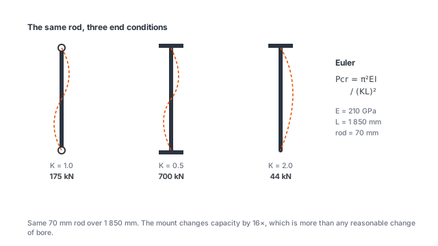
- Check the rod against buckling at full extension. The mounting type sets the effective length factor, and that factor changes capacity by a factor of sixteen between a fixed-fixed and a free-ended column — see the mounting guide for the worked example.
Speed, and why it is not independent
Velocity is flow divided by area, so the same pump produces different speeds at different stages:
v = Q / A
A pump delivering 60 L/min into the 158 mm stage gives 0.051 m/s, and into the 115 mm stage gives 0.096 m/s — nearly double. Multi-stage cylinders therefore accelerate through the stroke, and the full extension time is not the stroke divided by the first-stage speed.
For a single-stage cylinder, the cylinder speed calculator does this division for you, including the annulus side where the speed is higher.
Extension time is the sum of stage volumes divided by flow. For the underbody range, working volume is published directly — 8.5 to 14 L across the E130 series — so the time is that volume divided by your pump flow, with no need to integrate the stages.
The check that catches most sizing errors
Compare the theoretical force from F = p × A against the capacity shown in the model table for the same model. If they disagree by more than about 10 percent, one of three things is true: the pressure is not the one you assumed, the effective diameter is not the one you assumed, or the published capacity refers to tipping capacity at a linkage rather than cylinder force.
The third is the most common. Tipping capacity is the load the body can lift through its linkage, which is not the same as the force at the piston. Both numbers are useful; confusing them produces a cylinder that is either oversized or, worse, undersized by the linkage ratio.